DROPPER POST V2 SERVICE - REBUILD
Tools needed
- V2 Dropper rebuild kit (SP1C0053)
- Waterproof grease (ie. Slickoleum, Slick Honey)
- Rubbing alcohol
- 2 & 5mm hex
- Pick tool
- Needle nose pliers
- Strap wrench
- 14 mm or 17mm wrench (or adjustable wrench)
- Lint-free Cloth

COMPLETE EXPLODED VIEW & PARTS LIST

This service should take about 20 minutes and should be completed every 250-350hrs of riding depending on the conditions in which you ride. Always check your air pressure after servicing. The pressure should be 250-300psi when the post is fully extended.
Users are encouraged to perform regular maintenance earlier if required. If something seems rough or unusual after servicing please stop and contact info@oneupcomponents.com to avoid additional damage to the post.
STEP 1: SEAT CLAMP ASSEMBLY
Unthread rear clamp bolt (4) using your 5mm hex key. Remove clamp nut (1) & upper clamp (2). You can then remove your saddle & the lower clamp (3). Clean assembly and put aside until you have check the air pressure at the end of this service.
TIP: Leave front clamp bolt (4) & dont adjust it. When you reinstall the seat, torque the rear clamp bolt to 8Nm (70 in-lbs) and your seat angle will remain correct.

STEP 2: VALVE CAP OR COVER
Once seat cap assembly is removed, there will be either a rubber cover (5) or metal valve cap (5). Either can be removed by hand or with needle nose pliers to expose the cartridge lock ring (6).

STEP 3: REMOVE CARTRIDGE LOCKRING
Using a pair on needle-nose pliers unthread and remove the cartridge lockring (6).

STEP 4: REMOVE ACTUATOR FROM LOWER TUBE
Unscrew the bottom green actuator (16) from the lower tube (12) using your wrench.
- For V2.1 actuators use a 14mm wrench.
- For V2.0 actuators use a 17mm wrench.

Once free of the lower tube (12), you can slide the lower tube up the upper tube (7) to expose the cartridge (14) & actuator lock bolts (17).
Alternate route: With the cartridge lockring (6) off, the cartridge & actuator (16) can be pulled out from the upper & lower tube assembly. The upper & lower tube assembly can be set aside. Once the actuator has been removed (step 5) you can skip step 6 below.

STEP 5: REMOVE ACTUATOR FROM CARTRIDGE
Remove the 2 actuator lock bolts (17) using your 2mm hex key. You can then slide the actuator (16) & bumper (15) off the bottom of the cartridge (14).


STEP 6: REMOVE CARTRIDGE
Now that both the cartridge lockring & actuator have been removed, the cartridge can be pulled out the bottom of the dropper.

Note: The cartridge push rod is held into the cartridge (14) by the actuator (16). when the actuator is off, the push rod can fall out of the cartridge (14). You can either make sure the push rod stays within the cartridge during the service or you can remove it, wipe it clean and set it aside until re-installation.

STEP 7: REMOVE CARTRIDGE WASHER
The cartridge washer (13) is located around the cartridge air valve. Double check that this ring is not damaged and remove by hand or with a pick tool and set aside for reassembly.

Note: If you are only completing a cartridge swap, stop here and complete steps 1-7 in reverse order.
STEP 8: MID CAP ASSEMBLY
Unscrew the mid cap assembly (8) by hand or using a strap wrench and slide it up towards the seatpost head.


STEP 9: REMOVE LOWER TUBE FROM UPPER TUBE
Slowly slide the lower tube (12) down off of the upper tube (7). Clean out the lower tube with your cloth and set it aside until re-assembly.


STEP 10: REMOVE BUSHINGS
Start with the lower bushing (11), it is a split ring so it can be removed by hand and slid off the bottom of the upper tube (7).

The upper bushing (9) is also a split ring. so you can either remove it by hand now by opening it around the upper tube (7), or leave it until you have removed the guide pins (10) and slide it off the bottom of the upper tube.

STEP 11: REMOVE GUIDE PINS
Using a small pick, remove the three guide pins (10) from the upper tube (7).

STEP 12: REMOVE MID CAP ASSEMBLY
Slide the Mid Cap Assemby (8) off of the Upper Tube (7).

STEP 13: CLEAN & ASSESS
Remove old grease from upper tube (7). Clean upper tube with rubbing alcohol and allow to dry. If you are planning on re-using the bushings (9,11) & guide pins (10), clean them as well.

Now is the time to assess for wear. If the bushings (9,11) have any discoloration or marring it is recommended to replace bushings, guide pins, & mid cap assembly. These components are all availalble in the V2 DROPPER REBUILD KIT.

Dissassembly is now complete and you are ready for assembly.
STEP 14: INSTALL MID CAP ASSEMBLY
Apply a layer of light suspension grease around the inside of the rubber wiper seal (8b). Carefully slide mid cap assembly (8), rubber wiper seal first, onto the upper tube (7), past the guide pin slots roughly 50mm. Be sure to do this slow and as straight as possible to avoid damaging the DU bushing (8e) within the mid cap assembly. You can scratch it on the guide pin slots if your not careful.

STEP 15: INSTALL BUSHINGS & GUIDE PINS
Grease the inside of both bushings (9,11), the guide pin slots, & a small amount around the inside of the bottom bushing seat on the upper tube (7).
Slide the freashly greased upper bushing (9) onto the upper tube, by hand, until it is past the guide pin slots.
Slide the lower bushing (11) back onto the upper tube by hand. Ensure it is sitting comfortably in its seat at the bottom of the upper tube.
Place the guide pins (10) into their slots, by hand, on the upper tube. Make sure they are seated properly at the bottom of their slots.
Add a layer of grease to the outside of the bushings.

STEP 16: LOWER TUBE INSTALLATION & ALIGNMENT
Align the guide pins (10) with machined grooves in the lower tube (12). The Lasered logoing on the lower tube should be centered at the rear of the post. For reference, the two guide pin slots should line up with the outer edges of the ONE lasered logo, as pictured below. Push lower tube past guide pins (9) carefully to ensure they do not bend or jam. This action should feel smooth.

Push lower tube up until the cartridge is exposed at the bottom of the post.
STEP 17: MID CAP ASSEMBLY
Seat the upper bushing (9) into the top of the lower tube (12). Thread the mid cap assembly (8) into the lower tube and tighten by hand or with strap wrench.
STEP 18: INSTALL CARTRIDGE
Make sure cartridge washer (13) is properly in place.

Slide the cartridge air valve first into the dropper assembly until the valve is exposed at the top of the upper tube (7). Reinstall cartridge lockring (6) using your needle nose pliers.
STEP 19: INSTALL ACTUATOR TO CARTRIDGE
Push lower tube (12) up until the cartridge is exposed at the bottom of the post. Slide the bumper (15) onto the cartridge (14) shaft. If you removed the pushrod, now is the time to insert it back into the cartridge.

Slide the actuator (16) over the end of the cartridge (14). Install the lock bolts (17) making sure they slide through the grooves of the cartridge. Tighten the lock bolts using a 2mm hex hand tight.

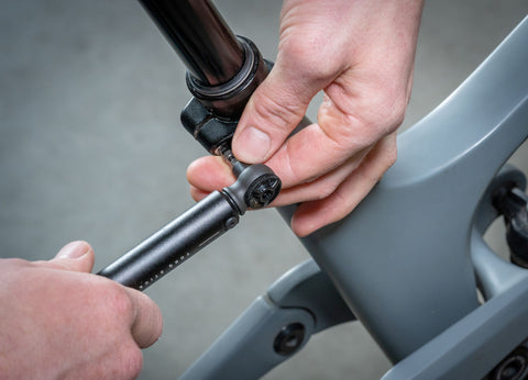
STEP 20: SECURE ACTUATOR TO LOWER TUBE
Thread the actuator (16) into the lower tube (12). Start slow by hand to avoid cross-threading. Once hand tight, use the wrench to snug the actuator to lower tube.
STEP 21: PRESSURE CHECK & INFLATION
Manually actuate post to max extension. Remove valve cap (5) by hand or with needle nose pliers. Attach Shock pump to valve. Inflate post to 250-300psi in the fully extended position.
Note: Because these cartridges are high pressure in a small volume, the equalization of the pump upon installation will produce a lower pressure reading than what was originally in the cartridge. This pressure loss can be as much as 50psi depending on the pump size and quality.

Remove shock pump and reinstall the valve cap (5) on the valve stem
.
STEP 22: SEAT CLAMP ASSEMBLY
Place lower clamp (3) into the cradle of the upper tube (7). Make sure the arrow is pointing forward. Place your saddle on the lower clamp. Holding your saddle, slide the upper clamp (2), arrow forward, under the front clamp nut (1) and place it on top of the saddle rails. You can then drop the rear clamp nut into its seat at the back of the upper clamp. Thread rear clamp bolt (4) into nut and tighten to 8Nm.
STEP 23: INSTALL POST ON BIKE
Clean out old FibreGrip or grease from the seat tube. Apply a fresh layer of fibregrip or grease to seat tube. Attached cable with barrel end to the dropper actuator. Carefully slide post back into seat tube while slowly pulling the remote side of the housing from the frame to aviod kinking the internally routed cable & housing. Set post to your proper ride height & torque seat post collar no more than 4Nm.

Congratulations, you have now successfully completed the V2 Dropper rebuild service.
NOW GO RIDE!
If you are having any problems please first double check that you have correctly completed each of the above steps.
If you are still having trouble please email us at support@oneupcomponents.com for help. Please include a detailed description of your issue. Photos are often helpful.
Thanks,
OneUp